Please read CyberSAGE Installation Manual before seting up CyberSAGE. Installation steps are different between regular and new users.
To quickly go through demo project, download CyberSAGE Demo Slides.
A more detailed version of this "CyberSAGE Quick Start Guide" is
available for download.
Advanced users may also want to refer to the "CyberSAGE Design
Document" which is also available for download.
Introduction
CyberSAGE modelling tool is able to process various heterogeneous pieces of information about a smart grid system such as its business processes, network infrastructure, adversary models and use this information to argue about the security level of the smart grid system. This enables a security analyst / practitioner to make intelligent decisions in order to protect the smart grid system which are under constant attacks by adversaries.
CyberSAGE provides the flexibility to create all the models within the tool itself. Alternatively models in .xml format created using other tools (Modellio for business process modelling, Microsoft Visio for network modelling, etc) may also be leveraged into CyberSAGE (However CyberSAGE in its present form does not support this feature but we expect advanced version of the tool to be more powerful). The backbone of the reasoning system implemented in CyberSAGE is a flexible Java based rules engine called Drools[1]. The rules engine allows advanced users to expand on the default capabilities of the tool. For example an advanced user may change the device properties (add new intrusion detection system protection) thus reducing the chance of it being attacked.
Installation and Configuration
System Requirements
CyberSAGE Version 1.0 is a platform independent application and it has been tested in WINDOWS-7, Linux and Mac. Please use the windows applicable installer or the platform independent compressed bundle file according to the Operating System/Platform as explained below.
Release Bundle |
File Name |
Operating System |
Java Version |
Windows Installer |
CyberSAGE-1.0.2.2.msi |
|
Java 7 or above |
Platform Independent Compressed Bundle |
CyberSAGE-1.0.2.2.tar.gz |
|
Java 7 or above |
Table 1 : Installation Options
System Installation
CyberSAGE is available for download from the project wesbite at https://www.illinois.adsc.com.sg/cybersage/CyberSAGE/download.html . A prospective user will need to fill in a request and send it to the CyberSAGE project team. Once validated a download link will be made available to the user via the email supplied in the requesting form. Please click here for more details on the licensing fees associated with CyberSAGE.
Platform Independent Installation :
Platform independent compressed bundle can be installed in any Operating System including Linux and Mac by following below steps.
- Download the Platform Independent Installation Bundle
- Move the compressed file to the installation folder
- Extract the compressed file. If you download the CyberSAGE version 1.1, extracted folder should at least contain two folders ( CSProject and log) with the executable JAR file ( CyberSAGE.jar )
- To run the CyberSAGE application execute the the below command in the console.
$ Java -jar CyberSAGE.jar
Windows Installation :
First time installation of CyberSAGE has only 3 easy steps as explained below. IF a different version of CyberSAGE is already present in the system, please make sure to uninstall it before initiating the new installation or you can let the installer to decide on how to replace the existing files.
Step 1 : Below screenshot shows the first step of the installation wizard. Press Next > to go to the next window of the wizard.
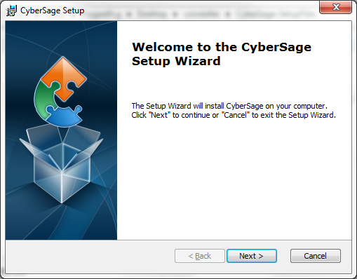
Figure 1 : Step 1 of the Installation Wizard
Step 2 : As given in the below instruction, Installation folder should be given in the Folder Text Field.
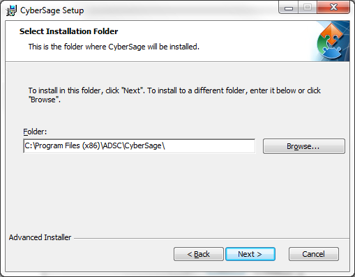
Figure 2 : Step 2 of the Installation Wizard
Step 3 : Press Install Button to begin the Installation of The cyberSAGE.
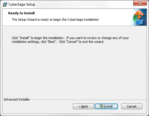
Figure 3 : Step 2 of the Installation Wizard
CyberSAGE windows installer will copy all the system
files into the installation folder and icons will be created in the
desktop and the program menu. CSProject folder
will be created in the first launch of the CyberSAGE and the two
sample projects will be copied to the same. CSProject/log
folder will contain the project specific properties to
store the working project path and the log files. After the
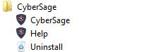
installation program menu will contain 2 links along with the
CyberSAGE launcher as below. User can easily uninstall the
CyberSAGE via the “Uninstall” menu option.
Please note that the uninstallation will remove only the installed program folders, files and icons. However, it will not remove any project files and related models. Therefore, user has to remove them manually or install a new CyberSAGE version to reuse them.
Welcome to CyberSAGE :
The first time CyberSAGE launches it displays a welcome screen giving useful hints to help the user get started.
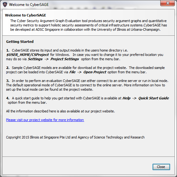
Figure 4 : CyberSAGE welcome screen
Configuration Details
The first time CyberSAGE is launched on a system it creates a couple of folders in the users home directory namely
i) $USER_HOME/CSProject directory to store the input and output models.
ii) $USER_HOME/CSProject/log directory for storing log files.
where $USER_HOME is the placeholder for the users home directory.For example on a typical windows system the $USER_HOME would evaluate to ``C:\Users\<user_name>``. The user does have the option to change the above directories via the Settings -> Change Project Settings option from the Menu bar.
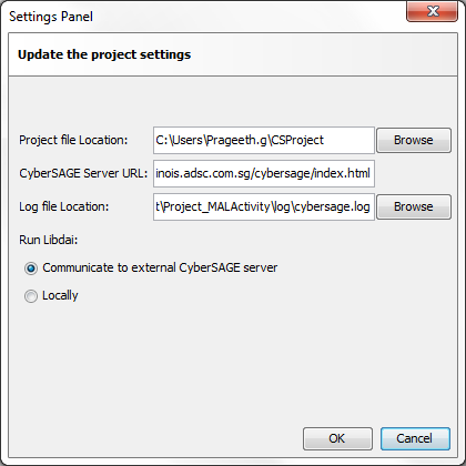
Figure 5 : CyberSAGE Settings Panel
In order to control the layout of the output models CyberSAGE makes use of a specialized graph layouting and optimization engine called `DOT` provided by the Graphviz library [3]. The DOT algorithm draws directed graphs as hierarchies. We discuss more about graph generation in the "Output Models" Section Also a combinatorial model is supported by CyberSAGE in order to obtain quantitative metrics for the generated graph.The combinatorial engine leveraged by CyberSAGE is called Libdai [4].The Libdai is a free/open source C++ library that provides implementations of various (approximate) inference methods for discrete graphical models. There are two possible ways in which the tool interfaces with the evaluation engine depending upon the mode of operation of the tool i.e.,
- Local mode: in this mode the tool user keeps a copy of the ``DOT`` and libdai binary called ``daifgpe`` on the local hard disk where the security assessment is being done. The need for building locally arises due to the fact that the libdai binary is platform specific. The instruction for building this binary is available at [2]. The user does not need to build the dot binary but use it as is provided after the installation of Graphviz.
- Remote mode: an alternative to approach described in a) is to host these binaries in a server and connect to them on demand akin to connecting to a web application. Since we are currently unable to provide platform independent libdai binaries, we favour this mode of evaluation and hence make this the default mode in CyberSAGE. However this method does suffer from the drawback that the user must have an active internet connection at all times to be able to interface with our server.
These two options are seen within the settings panel window as shown in Figure 2. An encrypted https session is created between the java client and the CyberSAGE server. The server upon solving the model returns back the rendered results for the java client to process. We do believe that certain organizations will be reluctant to allow the model data to leave outside the organizational boundaries. Hence future versions of CyberSAGE will allow libdai and dot binaries to be deployed locally and the URL for the same can be set via the ``CyberSAGE server URL`` field in the settings panel.
Preferences
The User can change the operation preferences in the Preferences window at Settings -> Preferences. Currently it has only one section to select the Docking Tool Preferences.
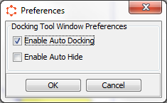
Figure 6 : CyberSAGE Settings Panel
CyberSAGE Version 2.0 provides dockable and floatable panels to improve user operations. When the Auto docking mode is enabled, system check each user operations in the middle canvas and display the most relevant panel as side panels. When the Auto Hide mode is enabled, system hide all the dock panels when the user click on the canvas.
System Files
CyberSAGE stores the input and output models on the local file system. The input models comprise of the workflow files, system topology files and the adversary model files. The workflow file describes the business process activity, the system topology file describes the network infrastructure information while the adversary model describes the attacker details. CyberSAGE internally represents each of the above in an xml structure.
The default location of the model files is $USER_HOME/CSProject. When CyberSAGE is run for the first time it sets up the directory structure with sample projects for the models out of the box. User can create new projects and the default project tree structure will be generated as shown below.
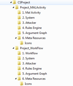
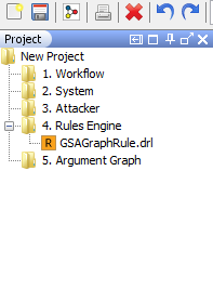
Figure 7 : CyberSAGE default directory structure
The legend of the Project Directories :
“Project_MALActivity” : This folder holds all the default project files related to Mal Activity Mode. If this folder structure is not available in the configured project path($USER_HOME/CSProject), It will be newly created by the system automatically.
``Project_MALActivity/1.Mal Activity`` : contains the input mal activity model files
“Project_WorkFlow” : This folder holds all the default project files related to Workflow Mode. If this folder structure is not available in the configured project path ($USER_HOME/CSProject), It will be newly created by the system automatically.
``Project_WorkFlow/1.Workflow`` : contains the input workflow model files
-``<Any Project>/2. System`` : contains the input system model files
-``<Any Project>/3. Attacker`` : contains the input adversary model files
-``<Any Project>/4. Rules Engine`` : by default it contains only one rule file ( As shown in Figure 7 above as GSAGraphRules.drl) which are the extension templates controlling the way the assessment graph is generated. The rules file are created based on the extension templates we describe in our graph generation papers and their related tech reports [5].The user is allowed to change these extension template files to adapt to the local execution environment.
-``<Any Project>/5.Argument Graph`` : contains the results of the assessment
-``<Any Project>/6. Meta Resources`` : contains a set of xml files (MetaProperty.xml, MappingRecord.xml, GSAProperty.xml & AttackerProperty.xml) which are used to initialize the CyberSAGE models. These are configurable via various editors within CyberSAGE, thus providing a flexible way to improve upon the default capabilities of the tool. CyberSAGE also ships with a library of general purpose icons/images kept here so that a user may adapt icons to his own needs. The user may alternatively make his own icons and drag drop here . These will be automatically resized and processed correctly by CyberSAGE when the user changes icons or adds new icons for the various CyberSAGE components .
NOTE : It is advisable to never delete these system files directly from the disk but let CyberSAGE take care of deleting and cleaning from within the application itself ( In CyberSAGE select a model by clicking on the left navigation tree and press the ``Delete`` key on the keyboard to delete the model from the navigation tree and the project workspace on the disk).
Getting Started
Create/Open a Project
The following sections will detail the steps to run an evaluation using CyberSAGE. For first time users of the tool the easiest option would be to jump to the "Argument Graph Generation & Evaluation" Section , download the sample input models, run an evaluation and see the results. Detailed descriptions on how to create the models within CyberSAGE itself and outlined in below sections.
New CyberSAGE Projects can be created by the “New Project” sub menu item under the File menu as shown in the Figure 8. New Project action will create the basic folder structure of the project with the project file (project.cs) and the extension template files.
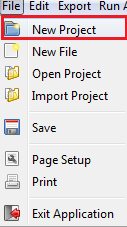
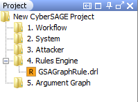
Figure 8 : The menu item (Left) to create a new CyberSAGE project with the project structure (Right)
First time users of CyberSAGE can quickly play with the copies of sample projects as basic tutorial guides. Sample projects will be delivered with the binary executables or they can be manually downloaded from https://www.illinois.adsc.com.sg/cybersage/, which contains all the input models in a zipped format. Upon download these can be directly imported into the CyberSAGE tool via the Menu -> Import Project options of the menu bar. The models will be automatically unzipped ** and loaded into the project workspace.
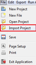
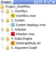
Figure 9 : Menu item (Left) to import a project and the imported sample project (Right)
Upon browsing to the location of the stored sample project and clicking ok we see an updated project navigation tree within CyberSAGE as shown above.
All CyberSAGE projects are associated with a project file in the project folder and its name should be project.cs. The “Open Project” menu item can be used to switch between CyberSAGE projects by selecting the project file. The name of the CyberSAGE project will be determined by the name of the project folder. Similarly, the “New File” menu item can be used to create new files by selecting one of three file types as below.
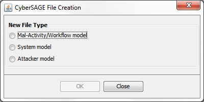
Figure 10 : New File Type Selection Dialog Box
As seen from the above figure, all the input models have been successfully loaded into the project tree. Click on any model in the project tree to see the graphical canvas being updated. Single click on each of the model files except the Rules file to load them into the drawing canvas.
Input Models
The various pieces of diverse information such as business processes, network topology and adversary information will be represented by CyberSAGE as input models. These will be used to initialize the graph generation engine. Let us discuss each of these models in the following sections.
Workflow Modelling
Workflows describe the business processes of a system. They represent a series of activity that need to be performed for the accomplishment of a given task. The default workflow model included in the sample project is a simple workflow detailing the interactions that take place a DMS and RTU in a smart grid environment. More complicated workflows with non sequential execution interactions are also supported by CyberSAGE and details for the same are available in the ``User Manual``.
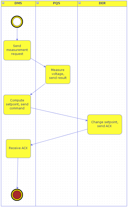
Figure 11 : Sample workflow model
System Modelling
A system model describes all the components of the proposed system under study. It is similar in concept to the network diagram of the system. CyberSAGE allows such models to be created within the application itself using specialized editors. Please refer to our ``User Manual`` on how to create such system models. The model included in the default project shows interactions between an abstracted set of components typically found in a smart grid environment.
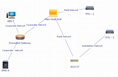
Figure 12 : Sample system model
Single clicking on any of the components of the system model will trigger the property sheet editor which allows user to change any of the default specified values.
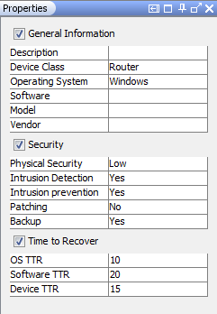
Figure 13 : Property sheet editor to update properties for device components
Attacker Modelling
Compared to the well-defined workflow and system models, CyberSAGE adversary models are less complex. In CyberSAGE we define an attacker from the perspective of the amount of resources (manpower, money) , level of access ( physical access or network access to systems) and the skillset (hacking capabilities) possessed by the attacker. We use this information to argue whether the devices in the system under study can be compromised by this particular attacker or not. We include two sample models in our default project, one of a fairly powerful attacker and the other of a fairly weak attacker.
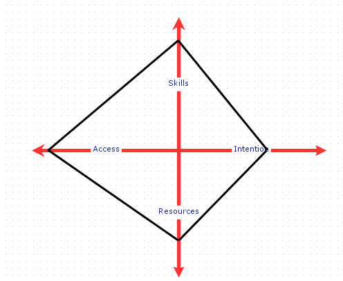
Figure 14 : Sample attacker model
Single clicking on any of the axis of the attacker model will trigger the property sheet editor which allows user to change any of the default specified values. There are 4 attacker profile dimensions as shown in the above radar chart.
- Skills : Various attacker skills required to perform a successful attack is modeled under the Skills Dimension. As shown in the below property panel there are 9 skills types in Two categories.
- Access : This includes two profile properties such as Physical Access level and the Logical Access Level. User can define the level by one of the three level types (LOW, MEDIUM and HIGH) using the given drop down box.
- Resources : There are various attacker resources such as Manpower and Arrival Rate, required to perform a successful attack is modeled under the Resources Dimension.
- Integrity : This dimension models the intention of the attacker based on three decimal property values correspond to Confidentiality, Integrity and Availability.
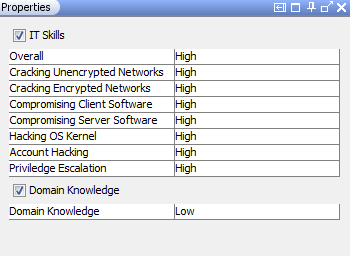
Figure 15 : Property sheet editor to update the skills capabilities of the adversary
Drools Rule Engine
As same as the activity models, extension template files can be loaded into the canvas drawing space by a single click on the extension template file in the project tree. Double click on the extension template file to load it in an external editor. You may edit the rules file or for the sake of simplicity keep using the sample ones that have been provided as is. User could choose XML model or design model when edit rule file.Drools extension template updation is a complicated procedure. Please refer to the technical report to obtain an in depth knowledge before making any changes to these meta files.
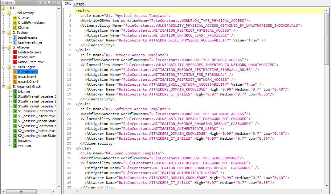
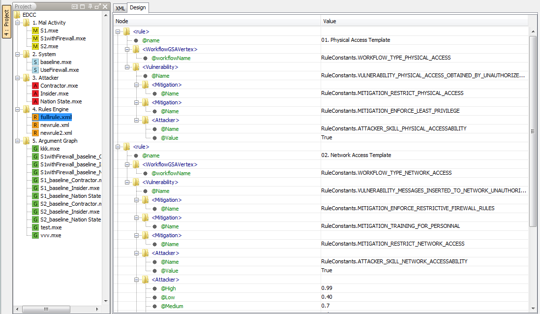
Figure 16 : Drools extension template files opened in the CyberSAGE
Argument Graph Generation & Evaluation
In order to run an evaluation for the specified input models you may select “Run Assessment” from menu bar and click ``Generate Argument Graph``.
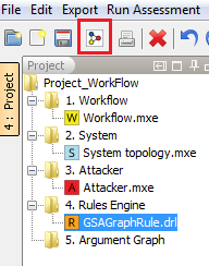
Figure 17 : Initiate an assessment by generating the GSA Gaph
Select the input models and the rule file against which the evaluation needs to run. The simplest rule file is the GGraphRule file which associates a goal to the workflow node, the GSGraphRule file associates the devices of the system model to the workflow nodes plus the capabilities of the GGraphRule file while finally, the GSAGraphRule file associates the attacker to the device plus the capabilities of the GGraphRule and GSGraphRule files.Lets select the GSAGraphRule file. Click on the ``Generate`` button to being the assessment process.
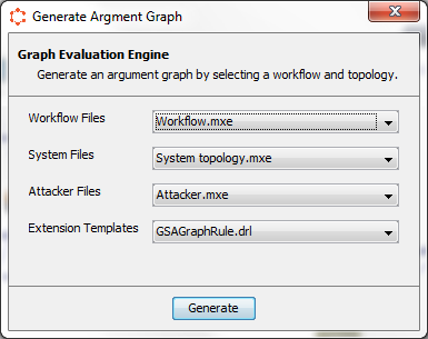
Figure 18 : Select the models and rule files to initiate an assessment
CyberSAGE is able to relate the workflow and system models via the mapping of the actors that operate on specific workflow steps to the corresponding devices in the system model. An incorrect mapping will result in inaccurate results being generated. The workflow actors are specified via names on the top of rectangular swim lines within which the workflow step is contained. For example in our sample project we have three actors namely DMS-A , RTU-1 & RTU-2. Select the correct mapping between the workflow steps and the device actors in the pop up dialog.
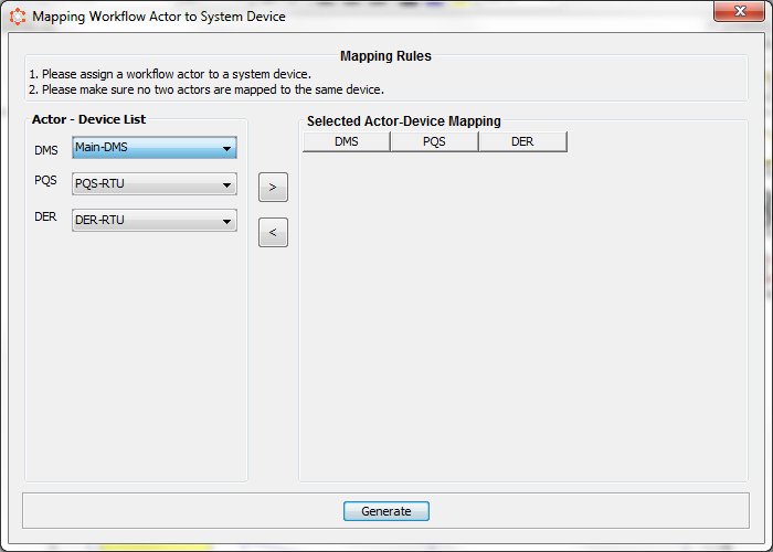
Figure 19 : Workflow Actor - Device Mapping default initialization
If you are running CyberSAGE for the first time the mapping table be shown as above and you will be expected to select the correct mapping via the dropdown comboboxes and save the mapping via “>” (Move Right) button. To delete the mapping, select the table row and press “<” (Move Left) button.
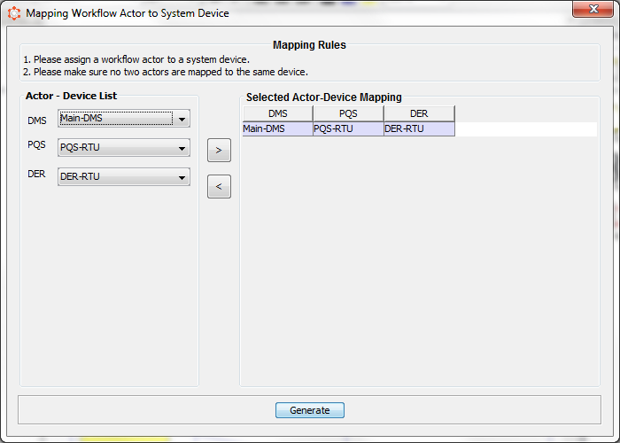
Figure 20 : Workflow Actor - Device Mapping
CyberSAGE is able to remember the mappings for the specified workflow - system model and hence subsequently the next time an evaluation is attempted the mappings will be reloaded. Click on ``Generate`` button to initiate the evaluation process.
Output Models
The evaluation process may take a few seconds (a rough estimate would be 10-15 seconds). If the evaluation is successful you will be prompted to provide a name for the output model. The resultant argument graph will also be loaded into the canvas area of CyberSAGE. If no graph is seen then you may need to see the log files for any diagnostic messages at $USER_HOME/CSProject/log or $USER_HOME/log.
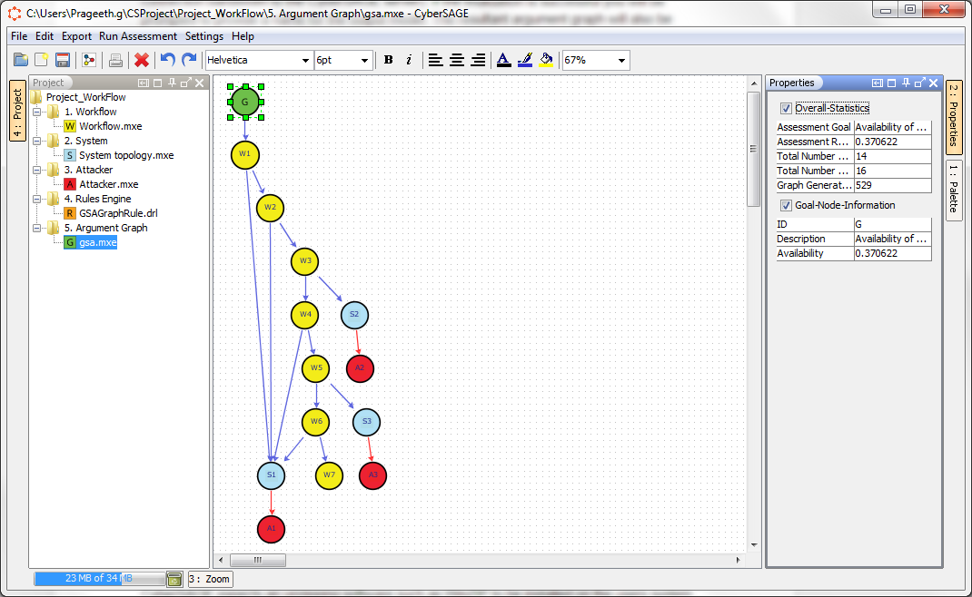
Figure 21 : Assessment result showing the argument graph on the canvas and evaluation statistics on the property sheet editor
CyberSAGE shows useful statistical information about every workflow, system and adversary node in the generated argument graph. Clicking on any of the node of the graph will update the property sheet with these per node statistics.
In order for the sample projects to be successfully loaded into the project workspace CyberSAGE expects an unzipping software such as WinZIP to be installed on the users system the absence of which will cause the importing of the sample project to fail.
The alternative to this would be to download some unzipping utility and manually unzip and place the model files in their correct folders at $USER_HOME/CSProject.
If upon double clicking the drools rule file, it does not open in any editor then it means that default editor of the system does not recognize a drool file extension (.drl is the extension for a drools rule file). In such case you may need to edit the preference settings of the default editor or alternatively go to the workspace location of the drools file i.e $USER_HOME/CSProject/<Project_Name>/4. Rules Engine and open the file in the default editor and permanently store the extension association. Another approach would be to update the registry.
Reporting
User can generate a report on a selected Argument Graph by the “Export Result” sub menu option in the “Export” menu as below.
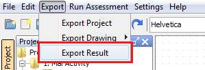
Figure 22 : The Menu Item to Export Evaluation Results to a Report
The cyber sage report will contain a basic outline as below. Please expect more sections with in detail low level analysis results in upcoming cyberSAGE release versions. Please email your ideas, suggestions and expectations, and we will consider them in future releases.
CoverPage : Contains the generated date and the argument graph file name
Overall Evaluation Result : Contains a summary of the overall probability evaluation result.
GSA Graph : Contains an image of the selected Argument Graph
Detail Evaluation Result Table : Contains table which explains each GSA Graph node along with their operation names and property values respectively.
Node Column : GSA Graph Nodes
Value Column: Process Name of the GSA Graph Node
Properties Column : Properties of the GSA Graph Node
More information
CyberSAGE design document
A more detailed document for CyberSAGE’s design can be found at: https://www.illinois.adsc.com.sg/docs/CyberSAGEDesignDocument.pdf
Feedback and support
HOME PAGE : Fore details on CyberSAGE project and support documents please access our home page at https://www.illinois.adsc.com.sg/cybersage/index.html.
CONTACT US : Please contact us at cybersage@adsc.com.sg if you have any feedback or need support to use the tool.
Uninstalling CyberSAGE
Uninstall in WINDOWS:
If you have installed CyberSAGE using the Windows Installer, please follow the below instructions to uninstall CyberSAGE in Microsoft Windows environment to remove installation files and registry entries.
01. Execute programs >> CyberSage >> Uninstall
02. Select yes in the confirmation dialogue box
03. Installer will remove all the files in the system directory.
NOTE: project files in the $USER_HOME/CSProject will not be removed automatically by the uninstaller, so that you can install another version and continue working on the same project files.
Uninstall in LINUX & MAC:
Please follow the below instructions to uninstall CyberSAGE if you have the platform independent version.
01. Delete all the System Files in the extracted or copied location manually.
02. Delete all the Project Files in the User Folder ($USER_HOME) manually
References
- Java Drools [http://www.drools.org/]
- Environment Setup for CyberSAGE https://www.illinois.adsc.com.sg/trac/wiki/Development%20Environment%20Setup
- Graphviz Library [http://www.graphviz.org/]
- Libdai: https://staff.fnwi.uva.nl/j.m.mooij/libDAI/doc/
- Nils Ole Tippenhauer, William G. Temple, An Hoa Vu, Binbin Chen, David M. Nicol, Zbigniew Kalbarczyk, and William H. Sanders. “Toward Automatic Argument Graph Generation for Security Assessment,” in Proceedings of the 20th IEEE Pacific Rim International Symposium on Dependable Computing (PRDC 2014). 2014.
- JGraph Library [http://www.jgraph.com/index.html]
- JGraph X github link [https://github.com/jgraph/jgraphx]
- JGrapht Library [http://jgrapht.org/]
- DesignGridLayout library [https://designgridlayout.java.net/index.html]
- Drools rule engine [www.drools.org]
 Copyright 2015 Illinois
at Singapore Pte Ltd
Copyright 2015 Illinois
at Singapore Pte Ltd